
[ MS12864GW01 ] dot matrix 3inch 128X64 COG Graphic LCD display
1,General Specifications
|
Item |
Contents |
Unit |
|
LCD type |
FSTN POSITIVE/NEGATIVE |
- |
|
Viewing direction |
6:00 |
O’Clock |
|
Module size (H´W´T) |
71.30X48.20X5.35 (excluded FPC length) |
mm |
|
Viewing area (H´W) |
66.50´38.00 |
mm |
|
Driver IC |
ST7565R |
- |
|
Number of dots |
128X64 |
- |
|
Backlight type |
4 LEDS White 3.0V 60mA |
- |
|
Interface type |
Serial Paraller interface |
- |
|
Operating temperature |
-20 ~ 70 |
oC |
|
Storage temperature |
-30 ~ 80 |
oC |
2,Interface Pin Connections
|
Pin no. |
Symbol |
Function(parallel) |
|
1 |
IRS |
This terminal selects the resistors for the V0 voltage level adjustment |
|
2 |
HPMB |
This is the power control terminal for the power supply circuit for liquid |
|
3 |
P/S |
This pin configures the interface to be parallel mode or serial mode. |
|
4 |
C86 |
This is the MPU interface selection pin |
|
5 |
V4 |
This is the MPU interface selection pin |
|
6 |
V3 |
|
|
7 |
V2 |
|
|
8 |
V1 |
|
|
9 |
V0 |
|
|
10 |
CAP2- |
DC/DC voltage converter. Connect a capacitor between this terminal and the |
|
11 |
CAP2+ |
DC/DC voltage converter. Connect a capacitor between this terminal and the |
|
12 |
CAP1+ |
DC/DC voltage converter. Connect a capacitor between this terminal and the |
|
13 |
CAP1- |
DC/DC voltage converter. Connect a capacitor between this terminal and the |
|
14 |
CAP3+ |
DC/DC voltage converter. Connect a capacitor between this terminal and the |
|
15 |
VOUT |
DC/DC voltage converter output. |
|
16 |
VSS |
Groud |
|
17 |
VDD |
Power supply |
|
18~25 |
D7~D0 |
The pin is the data bus to be connected to the MPU. |
|
26 |
RD |
This Pin is MCU interface input .This pin will be read signal |
|
27 |
WR |
This Pin is MCU interface input .This pin will be write signal. |
|
28 |
A0 |
This is connect to the least significant bit of the normal MPU address bus, |
|
29 |
RST |
When/RES is set to "L", the settings are initialized |
|
30 |
CS |
This is the chip select signal |
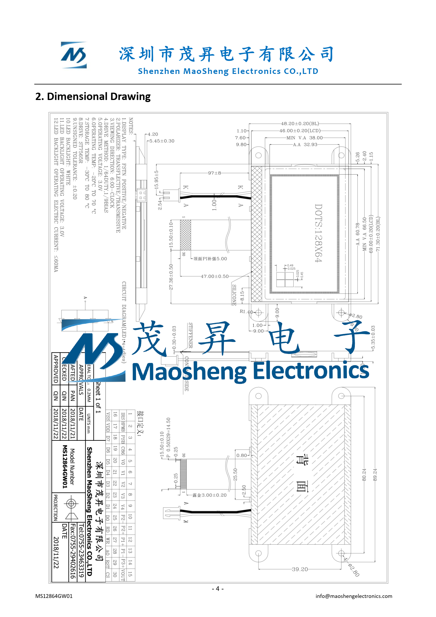
3,dimensions

4,
| Main Application | |
| Telecommunication Devices | Telephone, Interphone, watch, radio, etc. |
| H ome Appliances | Washing Machine, Refrigerator, Home Integrator |
| Industrial Control | Homotaxial Numerically-controlled machine tool |
| Instrument and Apparatus | Tester, Medical instruments |
| Vehical-mounted Digital | MP3, MP4 and vehical-mounted air conditioner |
| Mining | Mine's lamp charger, gas tester |
| Marine | Salinity tester |
For more details or any other request, pls contact whatsapp +86 18575525695 or info@maoshengelectronics.com .


